Antennentuner AT-100

Diesen Bausatz habe ich via AliExpress bezogen. Die Konstruktion stammt von N7DCC es gibt über das Netz verteilt ein paar Informationen diese Seite soll das etwas benutzbar zusammenfassen.
Der Tuner wird als fertig aufgebaut oder als teilbestückter Teilesatz angeboten. Beim Teilesatz sind alle SMD Bauteile bestückt. Der Anwender muß nur noch die Relais, Spulen und Stecker auflöten.
Es ist überaus einfach die Platine zusammen zu löten, wenn man beachtet den Lötkolben am kühlen Ende anzugreifen. Die einzige Herausforderung die man hat ist herauszufinden wie man die Spulen zu wickeln hat. Es gibt nur einen Platz der das Dokumentiert. Die diversen Textdokumente geben da keinerlei Hinweis.


Tuner AT-100

I got this tuner via AliExpress. The design is from N7DDC. There is soime Information available spread over the WEB. This page should give you an idea how to build and assemble it.
The Tuner is available as assembled board or as a kit. I bought the kit, which has a prepopulated board with all SMD components on it. The user has to complete the relays coils and connector.
It is pretty easy to assemble the board, as long as you bear in mind that a soldering iron is hold iron the clod side. The only challenge was to find out how to build the coils. There is only one place with a limited info in it. The existing documentation text documents do not give any hint.

Teilesatz
X

Teilesatz für den Antennentuner

Teilesatz

Teilesatz für den Antennentuner

 
Zunächst einmal zu den Informationsquellen:
Auf den diversen AliExpress Seiten gibt es den Antennentuner in mehreren Varianten, als Teilesatz, aufgebaute Platine und als Gerät mit Gehäuse. Weiters gibt es verschiedene Display Varianten und unterschiedlich viele Abstimmgruppen. Der Autor des Geräts hat das alles vorgesehen. Also genau schauen was man bestellt.
Auf den AliExpress Seiten sind manchmal ein paar Bilder verlinkt das wesentlichste ist der Schaltplan, nur auf diesem Dokument stehen die benötigten Wickelinformationen für die Spulen drauf.
Das (englische) Manual beschreibt das Gerät. Einige WEB Seiten besprechen das Gerät.
Die einzige Quelle mit detaillierten Infos über das Gerät mit dem Schaltplan ist auf easyeda zu finden. Dort findet sich auch die Tabelle mit den Bauteilinformationen wenn man das Gerät als Teilesatz gekauft hat.
First of all a few words about information sources:
There are several vendors on AliExpreaa offering this antenna tuner, in several variants. As part collection, assembled board or as finished device in a case. There are also several display variants available and 5-7 circuit groups. The designer of the tuner has prepares for all these variants.
Most of the AliExpress pahes just have a few pictures and a lousy variant of the circuit diagram. An important information is hard to find: how should the coils be done?
The manual describes the tuner. Some WEB sites discuss the tuner as well. There is only a single source which has solid design data. The circuit diagram with all details is published on easyeda. There are all details covered and the coil data is also there.

Schaltplan
X

Schaltplan als Bild

Schaltplan

Schaltplan als Bild

Schaltplan als PDF zum "reinzoomen"


Die Lieferung des Teilesatzes besteht aus einer Sammlung Bauteile, siehe Bild am Seitenanfang. Der Zusammenbau geht recht rasch. Relais sind eindeutig durch die Füßchen, die Elkos haben einen deutlich erkennbaren Polarisierung Aufdruck auf der Platine. SMA Stecker und Pfostenstecker Leiste ist in 20 Minuten mit Einlesen locker zu schaffen.
Danach habe ich die Spulen gebaut das hat dann über 2 Stunden gedauert. Für die Luftspulen habe ich Spiralbohrer als Körper zum Wickeln verwendet.
The shipment of the kit is a collection of components, see picture on page head. Assembly goes right fast. Relays have a clear footprint. The capacitors have a clear marking of the PCB. SMA connector and pole connectors, that's it. Preparation and soldering took less than 20 minutes.
Next building the coils took more than 2 hours. The circuit has all the details as text bock. 3 coils are air coils. I used a spiral drill as a base to wind the coils.

Luftspule
X

Bau einer Luftspule

Luftspule

Bau einer Luftspule

 
Die Ringkerne zu bewickeln hat sehr lange gedauert. Zum Verlöten auf der Platine habe ich dein Lack vom Draht herunter geschabt. Ein "runterlöten" des Lacks war nicht möglich weiters wollte ich den Kern nicht zu sehr aufwärmen.
It took a long time to wind the toroids. To prepare soldering I scratched off the paint. It was not possible to solder it off. Additionally I didnot want to warm the toroid up.


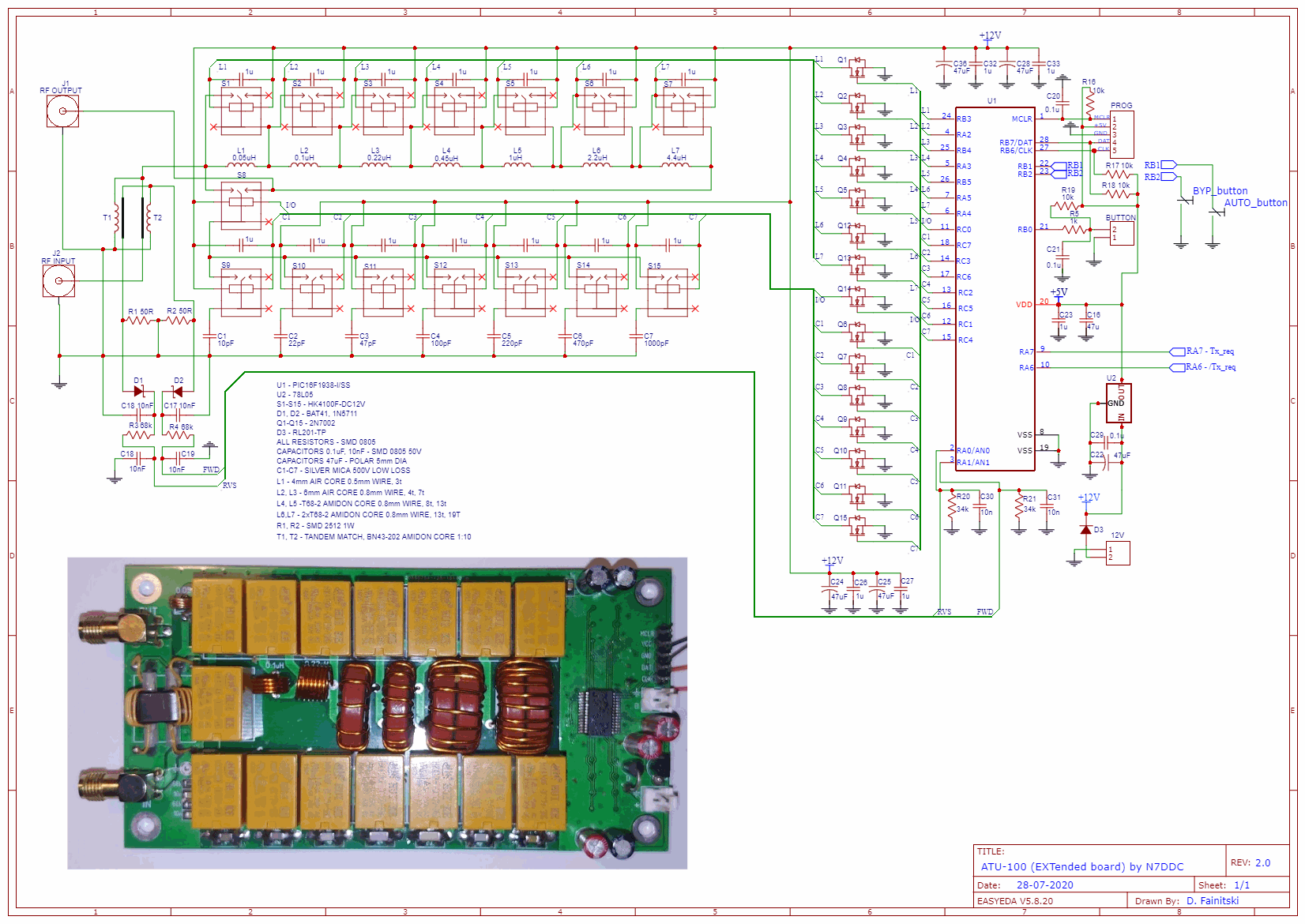
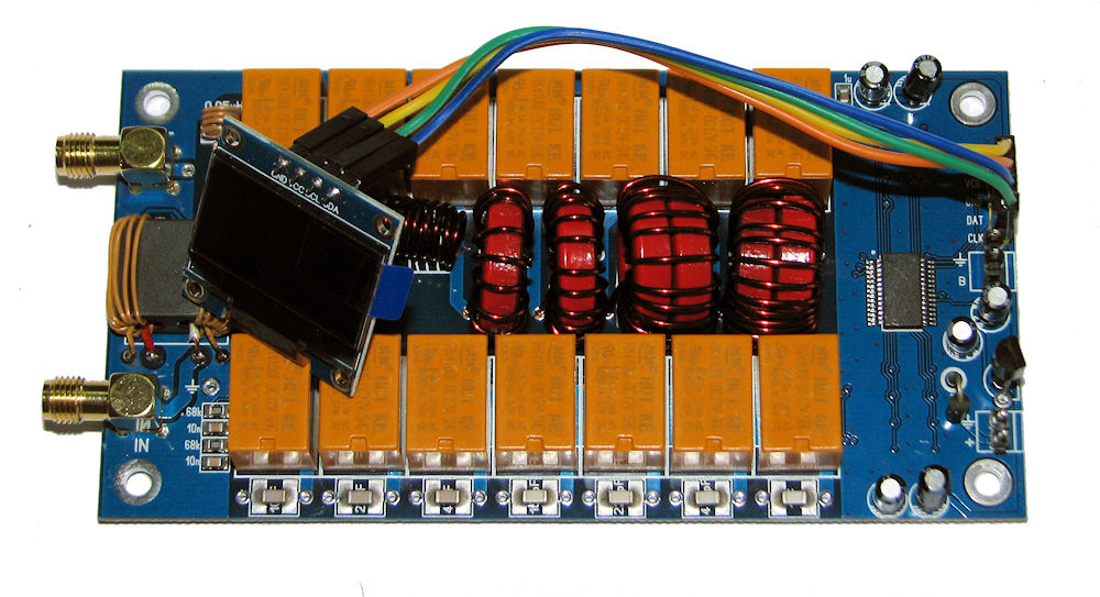
Die Werte der Spulen sind folgende:
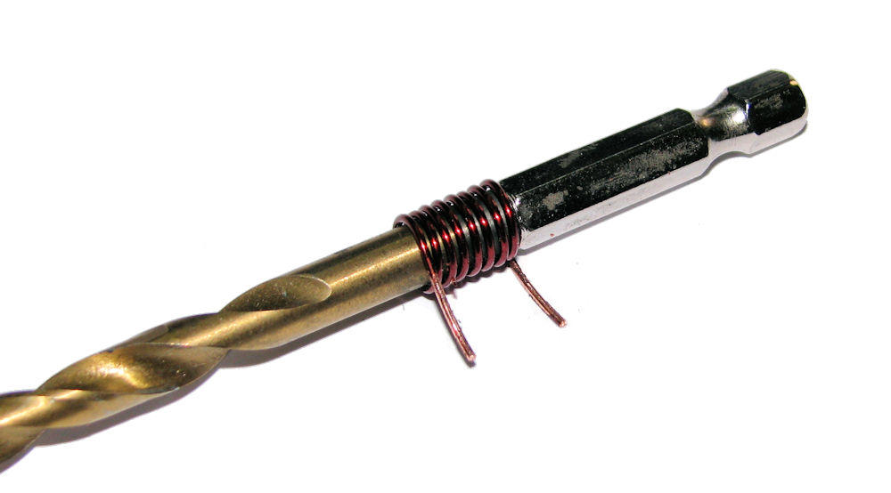
L1 Luftspule 0,5mm Draht 3 Windungen 4mm Duchmesser
L2/L3 Luftspule 0,8mm Draht, 4 bzw 7 Windungen 6mm Durchmesser
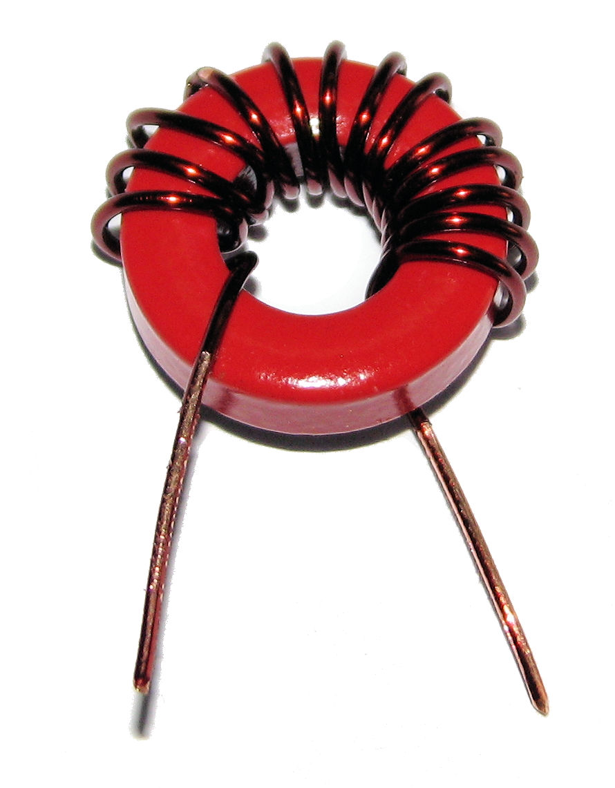
L4/L5 T68-2 Amidon Kern, 0,8mm Draht 8/13 Windungen
L6/L7 doppelte T68-2, 0,8mm Draht, 13/19 Windungen
T1/2 Tandem Übertrager BN43-202 Amidon Kern 1:10 - alle in gleicher Richtung


The coils have the following values
L1 air coil 0,5mm wire 3 windings 4mm diameter
L2/L3 air coil 0,8mm wire , 4 bzw 7 windings 6mm diameter
L4/L5 T68-2 Amidon core, 0,8mm wire 8/13 windings
L6/L7 double T68-2, 0,8mm wire , 13/19 windings
T1/2 tandem core BN43-202 Amidon core 1:10 - all in same direction

Luftspule
X

Spule auf Ringkern

Luftspule

Spule auf Ringkern

 
Die Platine war dann schnell fertiggestellt. Am nächsten Tag wurde dann noch das Gehäuse gefertigt.
The board was quickly finished. Next day I assembled the case.

Luftspule
X

Platine fertig bestückt

Luftspule

Platine fertig bestückt

 
Das Gehäuse besteht aus Aluminium Teilen. Die Durchlässe habe ich mit einem Schälbohrer ausgeweitet um die großen Löcher für die PL Buchsen und die 12V Buchsen zu bekommen. Direkt große Löcher bohren ist bei Blechen immer so eine Sache, es kann ausreißen oder das Loch wird nicht schön. Ein Stufenschälbohrer ist da einfacher. Für das Display das rechteckige Loch ist mit einer Modellbaustichsäge gemacht worden.
Die Vorderseite hat Passepartout bekommen um das Display schön abzugrenzen. Somit ist die Anforderung an die Bohr und Sägequalität nieder, zumal ich das Loch für das Display viel zu groß gemacht habe.
I use a aluminum case. The holes where drilled and then widened up with a hole cutter to get the large sized holes for the 12V connectors and the PL sockets. Drilling large holes directly tends to get dangerous and the holes are usually not nice. The rectangular hole for the display was made with a jigsaw. Actually I made it much too bog.
To get a nice front with ha sharp edge display frame I use a passepartout, so the quality requirement of the holes is actually not so high.

Gehäuse innen
X

Gehäuse offen

Gehäuse innen

Gehäuse offen

 
Die Frontseite ist eine schwarz lackierte 1mm Acryl Platte, das ich mit einem Laser Cutter geschnitten habe. An der Stelle des Displays ist die Schutzfolie auf der Acrylplatte auch angelasert worden. Zum lackieren ist dieses Stück Folie aber drauf geblieben. Nach mehrfachem lackieren und trocken ist das kleine Stück entfernt worden, übrig geblieben ist ein sauber abgegrenztes Fenster.
The front side is a black painted 1mm sheet acryl. I used a laser cutter to do this. At the display place I edged the protecting foil. To paint it I left that small patch in place. After painting I removed it and got a nice and clear window for the display.

Frontseite
X

Frontseite

Frontseite

Frontseite

 
Das Display ist von hinten an die Aluminium Wand angeklebt. Dazu verwende ich M2 Schrauben mit einer Mutter an der Vorderseite. Diese 4 Muttern sind an der Innenwand mit Super Kleber befestigt. Das ermöglicht ein späteres Entfernen des Displays so nötig. Die Montage erfolgt mit aufgesetzter Blende damit das Display korrekt positioniert ist.
The display is mounted on the front panel. I used M2 screws with nuts on both sides of the display PCB. The nuts are glued to the front panel. This allows to remove the display at a later time. Positioning the display was done by looking through the window and then securing the glue.
 

Die Kabel zum Display sind nicht 1:1. Das bunte Bandkabel zeigt daß blau und grün getauscht wurden. Die Belegung ist in der Beschriftung zu entnehmen. Der Pin MCLR bleibt umgeschaltet Vcc und GND ist ohnehin klar; Data-SDA und Clock-SCL.

The cable to the display are not 1:1 The colored cable in the picture shows green and blue are swapped. The pin MCLR is unused. Vcc and GND is more or less clear; Data-SDA and Clock-SCL that's all.

Gehäuse innen
X

Display Montage von innen

Gehäuse innen

Display Montage von innen

 
Das Gehäuse hat 2 Stromversorgungsbuchsen eine vorne und eine hinten damit man flexibler verkabeln kann. Weiterer Nutzen ist das Durchschleifen der Versorgung an andere 12V Kleinverbraucher. Ich habe da ein dünnes Kabel verwendet daher ist der Strom eher in Grenzen zu halten.
The case has two 12C connectors one in Front one in the rear side to enable flexible cabling if needed. Another option is to run power through to the next low power device. I have used a small gauge wire so amps are limited.

Display
X

Display während dem Tunen

Display

Display während dem Tunen


Display
X

Display nach dem Tunen, Antenne angepasst

Display

Display nach dem Tunen, Antenne angepasst

 
Einige Zeit nachdem diese Seite online war hab' ich erfahren daß die chinesischen Kits auf einem open HW/SW Projekt basieren. Hier der Link dorthin: https://github.com/Dfinitski/N7DDC-ATU-100-mini-and-extended-boards.
After this page was online I found out that this tuner is based on a open HW/SW project. Here is the link: https://github.com/Dfinitski/N7DDC-ATU-100-mini-and-extended-boards.
 

Abmessung

Die Abmessung der Platine ist 60 x 120 mm

Size

The board sizte is 60 x 120 mm


© OE1IAH 2019ff site wide page calls since 2019-06-09: 1860676

published on: 2022 08 28