QRP Magnetic Loop

Diese Antenne habe ich via Ali Express bezogen. Es gibt mehrere Anbieter sehr leicht zu finden. der Preis war Anfang 2021 knapp über €100,-

QRP Magnetic Loop

I have sourced this antenna via AliExpress. There are several vendors offering the antenna. I bought is for a bit more than €100,- early 2021.
 
Das überraschende an dem Angebot war für mich die beanspruchten Bänder 40m bis 70cm. Da schrillen sämtliche Alarmglocken, die Wunderantenne kann alles ist klein und leicht kostet wenig. Das will jeder haben - zugegeben ja auch ich. Der Mousepointer ist Wochen lang über den <KAUFEN> Button gekreist, irgendwann hab' ich dann doch geklickt.
The surprising technical clame of this antenna is to cover 40m to 70cm. All alarm bells started ringing extremely loud! I guess everybody is in search of this magic thing. Of course it triggered me immediately. I spent a few more weeks hovering my mouse pointer and finally I gave up and ordered it.

QRP Loop
X

QRP Magnetic Loop Teile


QRP Loop

QRP Loop

 
Die Antenne wird in einem Beauty Bag geliefert. Jeder der öfter in Asien einkauft kennt diese kreativen Verpackungsideen. Das ist bei vielen Produkten oft so, fördert das Misstrauen! Was hab' ich mir da eingetreten?
The antenna is shipped in a beauty bag. Everybody who orders frequently from Asia knows the habit to use packaging from other product areas. Of course not really improving my skeptic.

Tasche
X

Tasche


Tasche

Tasche


Tasche
X

Tasche offen


Tasche

Tasche

 
Die Tasche enthält den Ring aus einem KoaxKabel das Anpassglied und überraschend viel an Zubehör.
  • Coax Ring
  • Tuner
  • Mantelwellensperre
  • PL->BNC
  • PL Eckverbinder
  • PL-PL m/m Konverter
  • Ministativ
The bag contains the ring made out of a coax cable, the network and surprisingly some more parts.
  • Coax ring
  • Tuner
  • Common Mode toroid
  • PL->BNC
  • PL corner
  • PL-PL m/m gender changer
  • Tripod

Stativ
X

Ministativ


Stativ

Stativ


Stativ
X

Teilesammlung


Stativ

Teile

 
Die zentrale Tuner Box hat mehr Flansche als HF aktive Teile. In dem Kistchen ist im Wesentlichen der Schalter und 2 Drehkondensatoren. Die Drehkos sind die häufig benutzten kleinen Folienbauteile. Daher ist die Spannungsfestigkeit begrenzt das führt zur Begrenzung der Leistung die die Antenne aushält.
The tuner box has more connectors than HF active components. Inside the box there is the switch and two adjustable capacitors. Those capacitors are the well known small parts. They can't handle much voltage therefore this antenna can not handle high power.

Tuner
X

Tuner


Tuner

Tuner

 
Der Strahler ist ein Koaxkabel das am Ende je einen PL Stecker montiert hat. In der Matchingbox sieht man es wird auf beiden Seiten nur der Außenleiter kontaktiert. Ist ja klar im inneren des Kabels kann es keine Abstrahlung geben.
The antenna is a coax cable which has 2 PL connectors on each end. Opening the matchbox showed that only the outside of the cable is connected. This is clear inside of the coax there is no chance to send off.

Tuner
X

Koax Ring


Tuner

Koax

 
Das Innenleben der Antenne muß ich mir noch rauszeichnen. Es ist überraschend einfach gestaltet.
The inside of the box is really simple. I need to draw the diagram. Surprisingly few components there.

Innenleben
X

Innenleben


Innenleben

Innenleben

 
Nachfolgend ein paar SWR Bilder erstellt mit dem SWR Messmechanismus des IC705 bzw mit dem FA VNA.

Die ersten Versuche waren zunächst auf 70cm und 2m weil ich da faktisch kein Vertrauen hatte. Die lokalen 70cm Relais konnte ich mit 0,5W öffnen mit perfekten Quality Reports der QSO Partner. 2m ging auch wegen der lediglich verfügbaren 5W nur die interne Batterie benutzend nur in bestimmte Richtungen.
Next I present some SWR pictures which I dis using my IC705 and the FA VNA.

My very first try was on 70cm and 2m. I had no trust in the claim the antenna will work there. I was able to open local repeater with just 0,5W on 70cm and I had connections on 2m to specific stations. OK the 5W max power of my C705 on internal battery do not allow more.

SWR
X

SWR auf 145.500


SWR

SWR 2m


SWR
X

SWR auf 14.100


SWR

SWR 20m


SWR
X

SWR auf 7.090


SWR

SWR 40m


SWR
X

SWR auf 7.100


SWR

SWR 40m

 
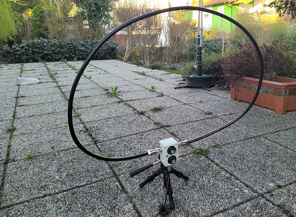
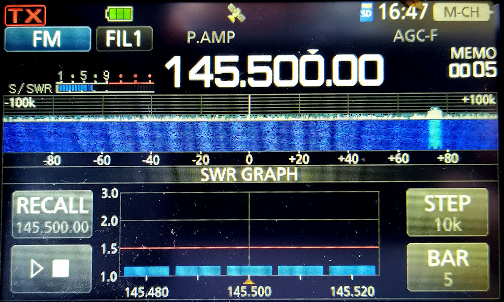
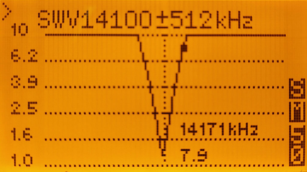
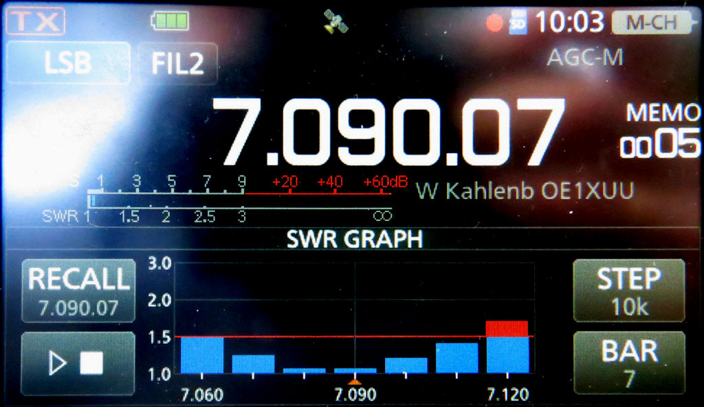
Man sieht auf den obigen Bildern die Antenne ist extrem schmalbandig die Antenne ist, typisch für eine 
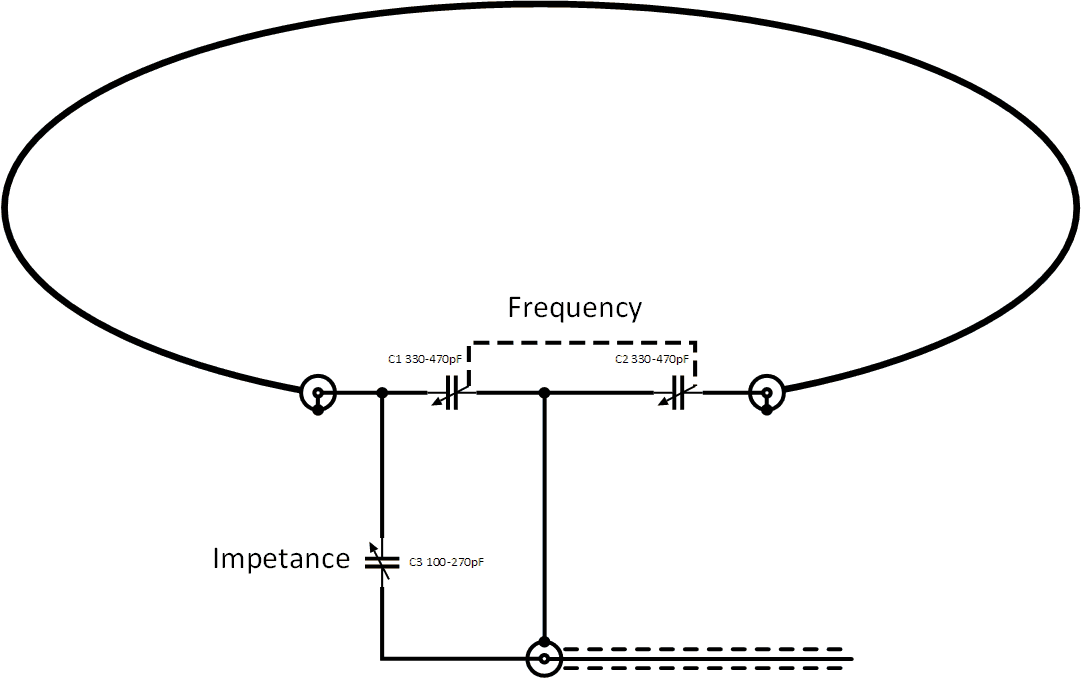
Loopantenne. Man muß, wenn man übers Band dreht, ziemlich bald die Antenne nachstimmen.
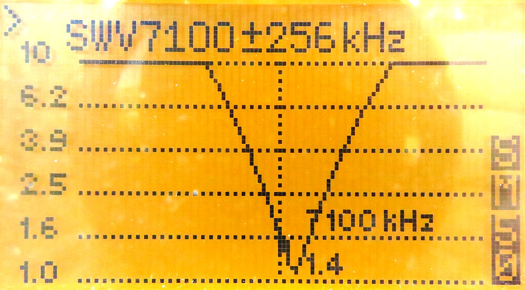
Das Nachstimmen ist überaus heikel, bereits kleine Drehbewegungen verursachen dramatische Änderung im Verhalten.
The pictures above show the antenna is extremely narrow. Quite typical for a loop antenna. It is necessary to trim the antenna while moving over the band.
Trimming the tuner is quite difficult. Even small movements on the capacitors have a dramatic influence on the antenna behavior.
 

Abstimmen der Antenne

Das Abstimmen der Antenne ist überaus heikel. Der obere Knopf beeinflusst die Frequenz auf der die Antenne arbeitet. Der untere Drehregler bestimmt die Impedanz. Zunächst ist anzumerken das Einstellen auf beiden Reglern ist überaus heikel. Bereits kleinste Bewegungen verursachen große Änderungen. Beim Nachtrimmen der Impedanz wird die Frequenz stark beeinflusst. Daher muß man zum Abstimmen für eine bestimmte Frequenz mehrfach beide Knöpfe verdrehen.
Das Abstimmen geht am leichtesten mit einem Antennen Analysator. Ich habe am Beginn um einige 100kHz falsche Resonanzpunkte gehabt. Mit dem VNA die Nadel nach unten dort hin schieben wo es sein soll und die Impedanz anpassen. Wenn das einigermaßen dort ist wo es sein soll kann man am VNA kleineres Band einstellen und fein tunen.

Für 2m und 70 CM stellt man den oberen Drehregler ganz nach rechts auf Anschlag. Es wird dann nur am unteren Regler die Impedanz getrimmt. Für die UKW Bänder muß der Schalter auf untere Position eingestellt werden.

Um in Stresssituation nicht all zu sehr verwirrt zu sein, habe ich die Vorderseite mit P-Touch Streifen beschriftet. Siehe "Portraitfoto" der Matching Box.

Trimming the Antenna

Trimming the antenna is extremely difficult. The top knob defines the frequency where the antenna is resonant. The lower knob sets the impedance. I want to note here even small movements on the nob cause big changes. Trimming the impedance changes the frequency as well. So it's necessary to use both nobs alternatively, several rounds.
Trimming the antenna is easy using an antenna analyzer. When I started I identified a misalignment of several 100kHz. So I used the VNA to move the spike down to the band where I wanted to operate. When I reached the desired area I switched over to a more narrow bandwidth setting and continued to optimize.

For 2m and 70cm the upper nob needs to be in rightmost position and the switch in lower position. The lower knob is used to optimize impedance.

To avoid irritation of the nobs I have labeled them with P-Touch strips. You can see the labeling on the "portrait picture".
 

Schaltungsprinzip

Das Scahltungsprinzip koppelt das Signal über Kondensatoren in die Schleife. Am Beginn und Ende der Schleife sind auch bei QRP bereits 1000V zu erwarten. Also nicht berühren wenn gesendet wird. Hier gibt es keine Koppelschleife im Inneren des Antennenrings wie das sonst häufig bei Loop Antennen gemacht wird. Die Kondensatoren müssen die Spannung aushalten konnen. Daher ist das nur im QRP Bereich üblich weil die Spannungen mit höherer Leistung auch stark steigen.

Circuit Principle

The circuit couples HF via capacitors into the loop. The loop connectors have a voltage of 1000V or more, so don't touch it. This design has no inner coupler loop ring as it is often used in other designs. It is easier to build, but the capacitors need to handle the high voltage so it is only used on QRP antennas, as voltage increases on higher power.

SWR
X

Schaltungsprinzip Kopplung über Kondensatoren


SWR

Schaltungsprinzip


© OE1IAH 2019ff site wide page calls since 2019-06-09: 1867618

published on: 2021 05 02