Die Antenne soll von 40m bis 10m arbeiten.
Man darf bei den langen Bändern wohl nicht sehr viel erwarten.
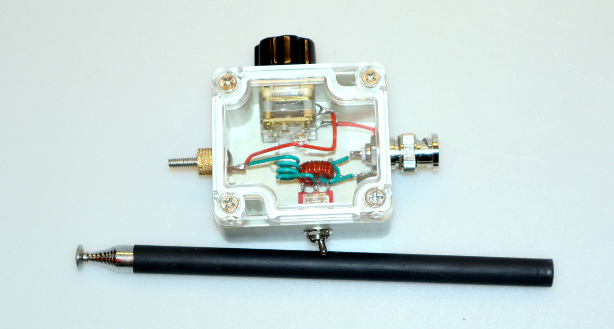
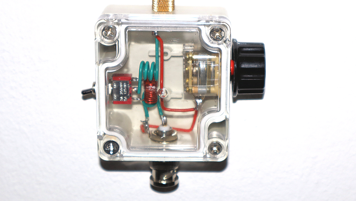
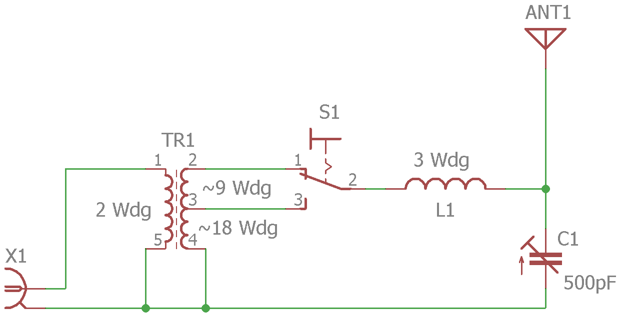
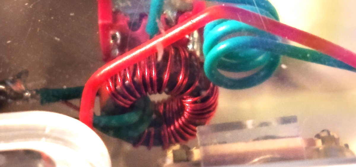
Die Schaltung ist ein Klassiker Übertrager mit einer Anzapfung im Sekundärkreis
Richtung Strahler. Die Anzapfung wird über einen Schalter seitlich umgeschaltet.
Parallel zur Sekundärspule ist ein Drehkondensator zur Abstimmung im Band. Dieser
Kondensator ist extrem "giftig". Nur eine sehr feinfühlige Bedienung des Kondensator
Drehknopfs erlaubt das Auswählen der Resonanzposition. Ohne Messgeräten nur mit zuhören
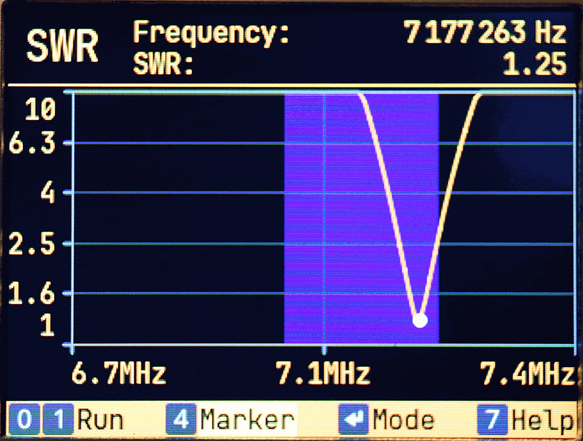
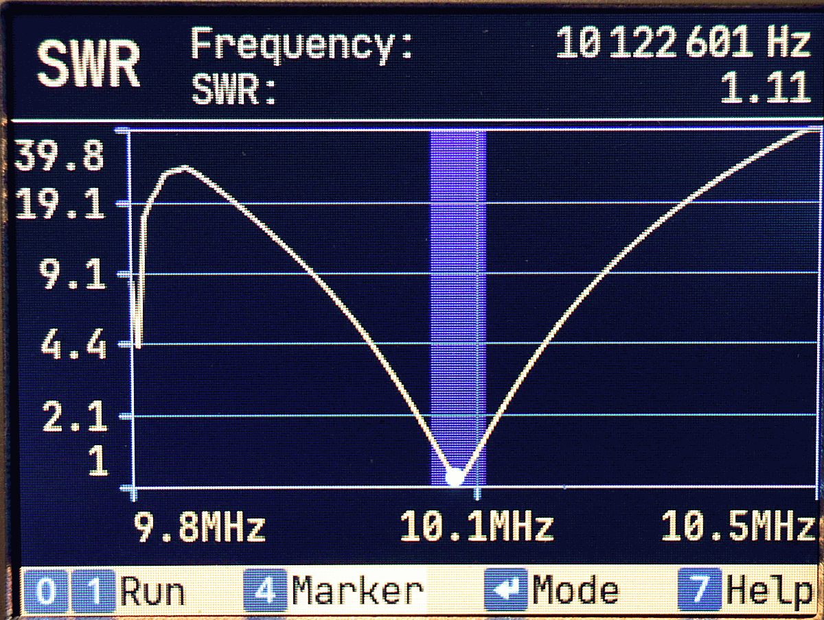
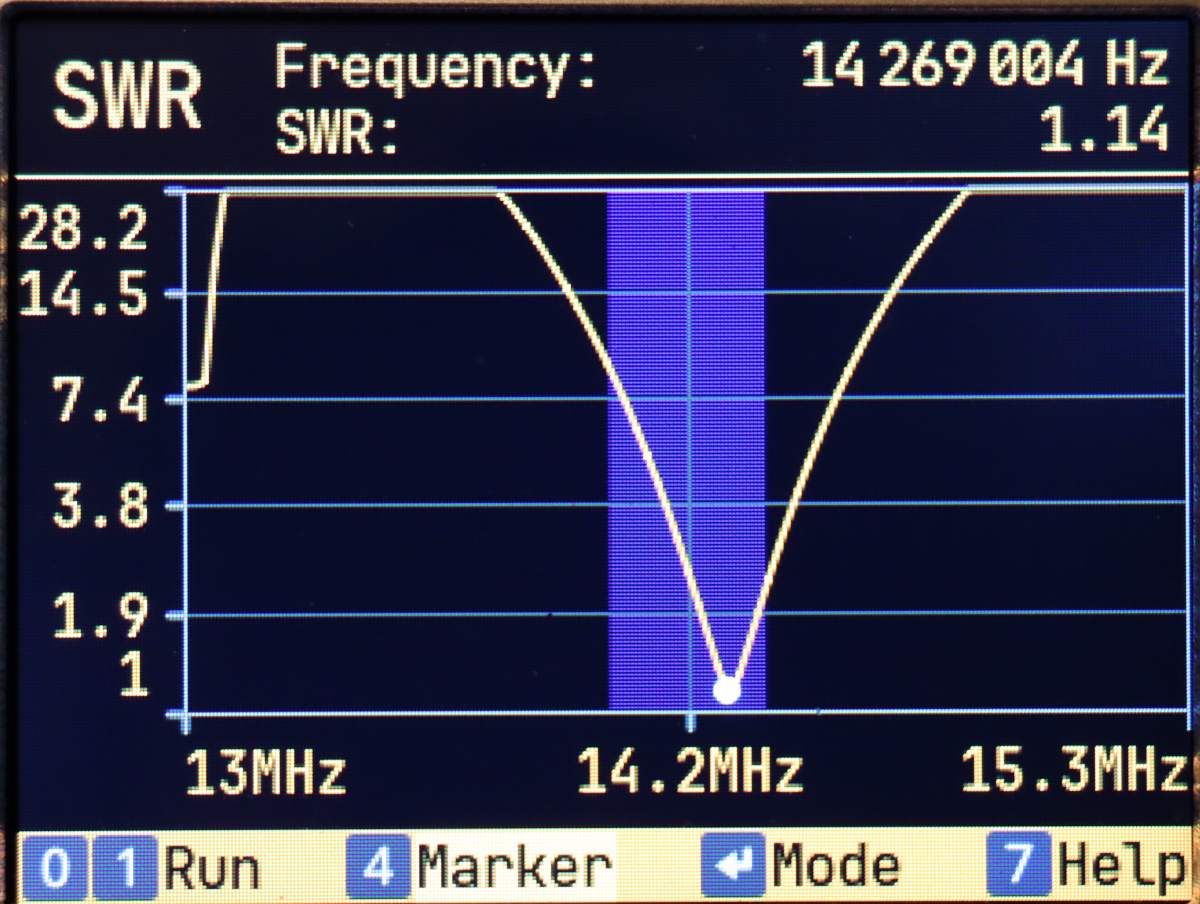
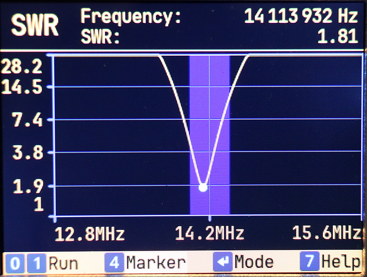
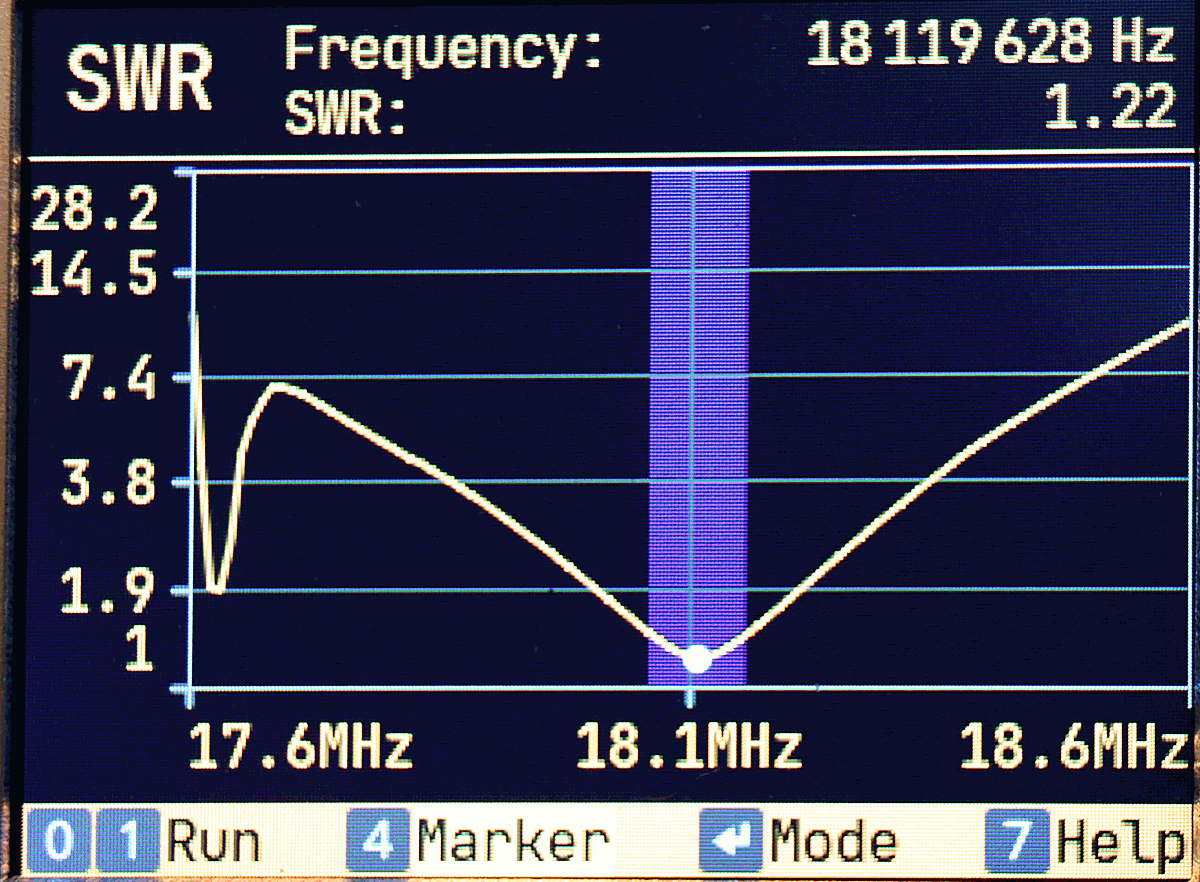
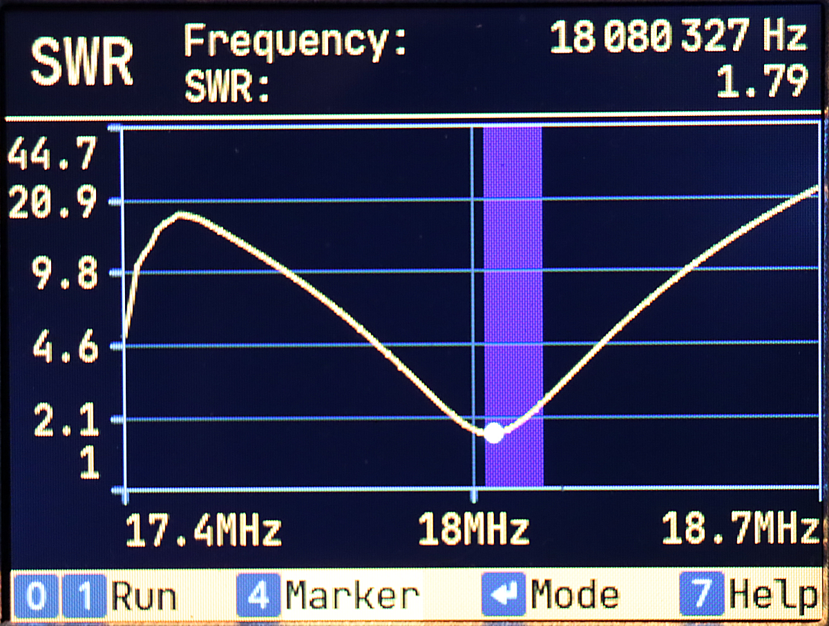
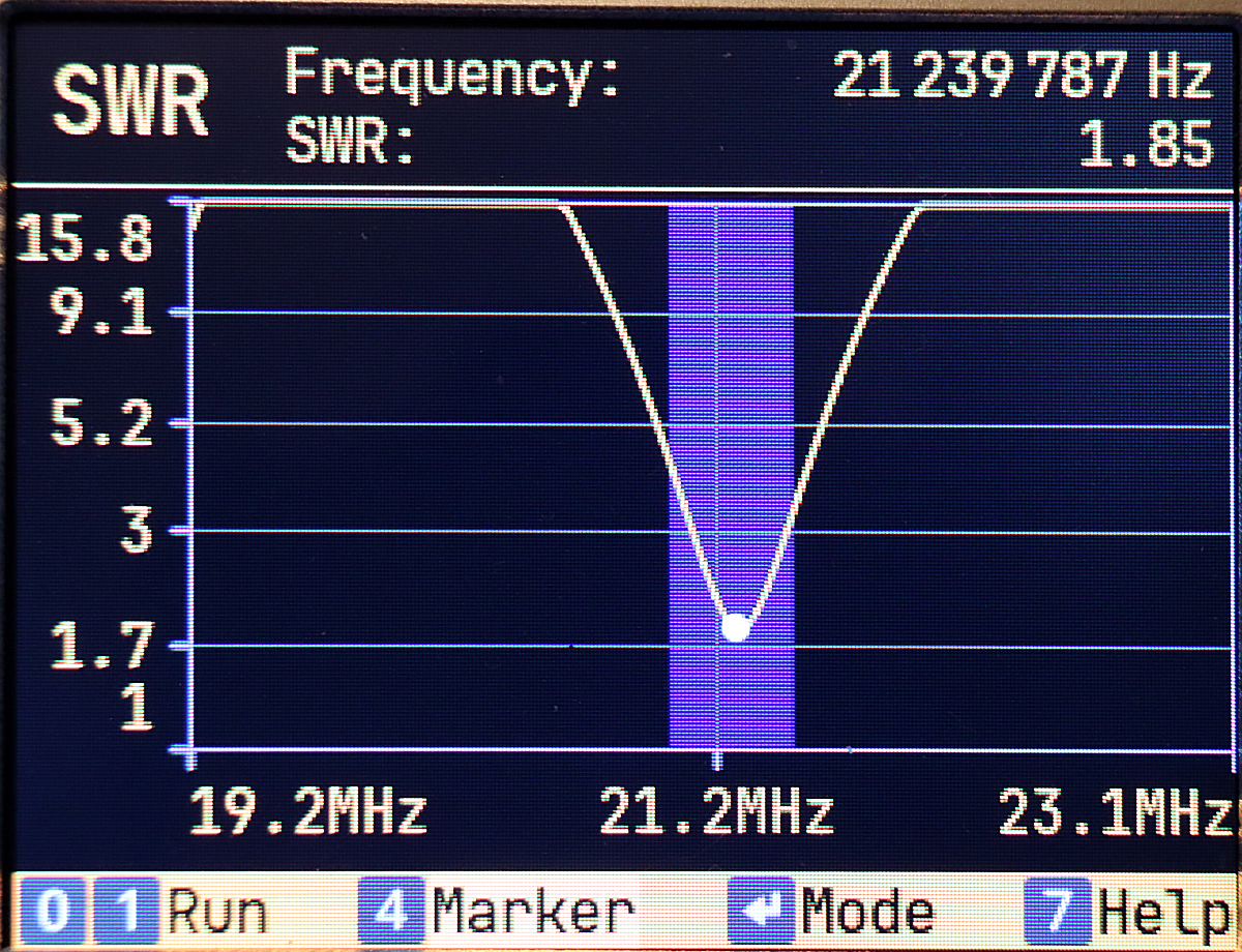
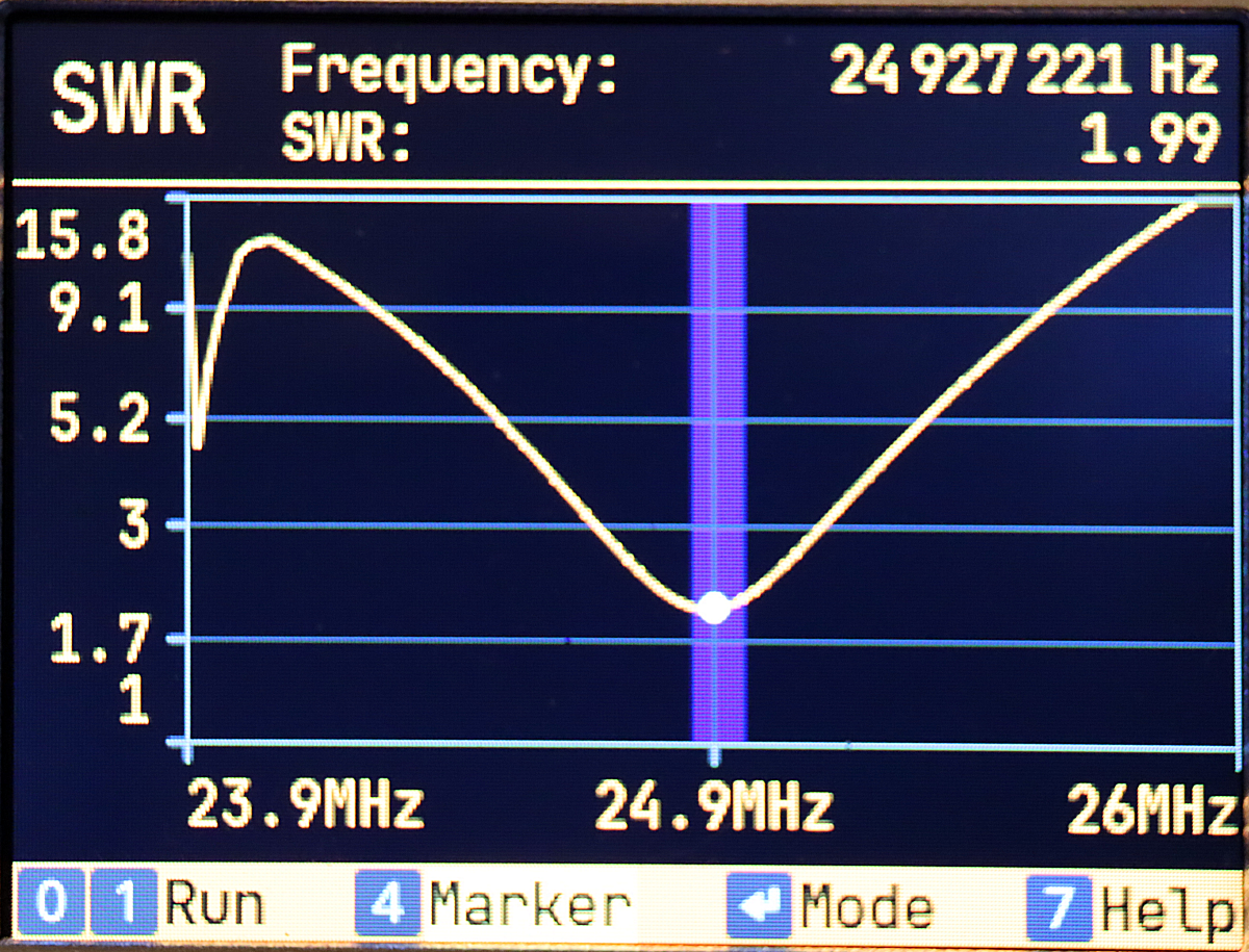
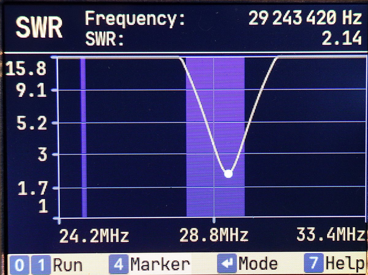
wird das sehr schwierig eine gute Position im Band zu finden. Die unten stehenden Bilder
von Messungen an der Antenne zeigen auch daß die SWR Werte zwar unter 2 zu bringen sind
aber Respektabstand von 1 halten.
Die Ursprünge der Fuchs Antenne hatten nur eine Spule mit Anzapfung und Drehkondensator
als Schwingkreis. Damals war der Sender durch die Röhrentechnik hochohmig. Für das heutige
50Ω System nutzt man einen UNUN zur Impetanzanpassung. Der Schwingkreis der Antenne
ist einerseits Teil der Anpassung aber auch ein Filter für das genutzte Band. Die echte
Fuchskreisantenne basiert auf langen Strahlern, den gibt es hier nicht. Die Antenne nutzt
aber die Idee den Strahler über einen Schwingkreis anzuspeisen. Zusätzlich wird hier auch
die Anpassung an den viel zu kurzen 1,6m langen Strahler gemacht.
The antenna is intended to operate from 40m to 10m. One shouldn't expect
too much on the longer bands.
The circuit is a classic transformer with a tap in the secondary winding towards the radiator.
The tap is switched via a side switch. A variable capacitor is connected in parallel to the
secondary coil for tuning within the band. This capacitor is extremely sensitive. Only very
precise adjustment of the capacitor knob allows selection of the resonant position. Without
measuring instruments, relying solely on listening will make it very difficult to find a good
position within the band. The images below of measurements taken on the antenna also show
that while the SWR values can be reduced below 2, they maintain a respectful margin of 1.
The original Fuchs antenna consisted of only a coil with a tap and a variable capacitor
as a resonant circuit. Back then, the transmitter had a high impedance due to the tube technology.
For today's 50 Ω system, a UNUN is used for impedance matching. The resonant circuit of the
antenna is both part of the matching process and a filter for the band used. The original Fuchs
antenna uses a long wire. Here the resonant curcuit also matches the too short transmittig rod.