Digitenna

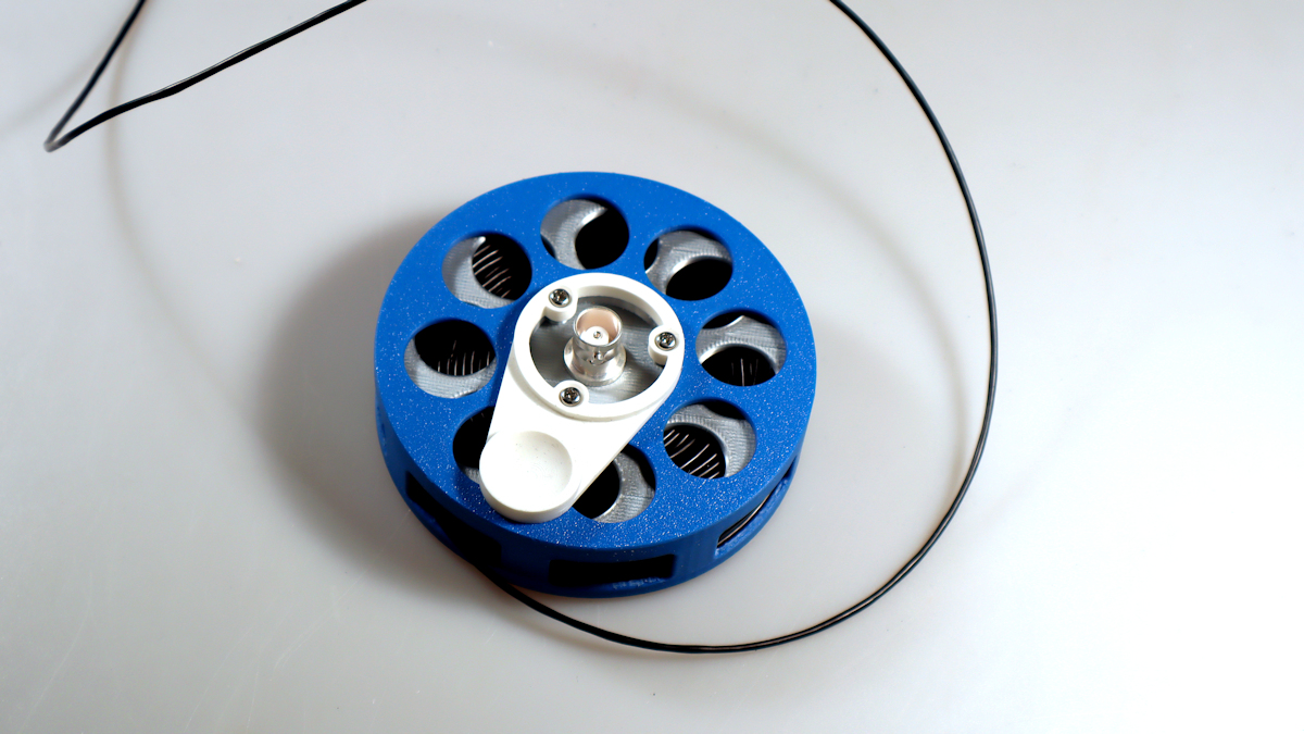
Nachfolgend eine weitere Form der Fuchs Antenne. Ich habe dieses Konzept schon einmal gebaut. Hier nun eine andere Variante. Der Wickelkörper ist ein 3D Druck Modell das man auf printables.com erhalten kann.


Fuchs Antenna on Wire Drum

Below is another form of the Fuchs antenna. I've built this concept before. Here's a different version. The coiled body is a 3D printed model that can be obtained from printables.com
 
Der Aufbau der Antenne ist vom Autor auf einem YT Video gut dokumentiert. In dem Video ist das Wickelverhältnis des Trafos schwer zu erkennen. 3 Primärwindungen die dann 20 Sekundärwindingen übertragen werden. Das Übersetzungs Verhältnis ist daher irgendwo zwischen 1:49 und 1:64.

Zunächst habe ich den Ringkern mit Teflonband isoliert um allfälligen Beschädigungen des Kupferlacks vorzubeugen. Die Spannungen im Fuchskreis können hoch werden. Die Antenne ist Endgespeist, also im Spannungsbauch.
Assembly of this antenna is documented in a slide deck of OE1WBS. Here is the report of my assembly:

First of all I insulated the core with teflon tape. It should avoid shortcuts if the wire insulation gets damaged. Voltage in the Fuchs circuit is usually high. The end fed antenna is connected at the voltage high.

kern
X

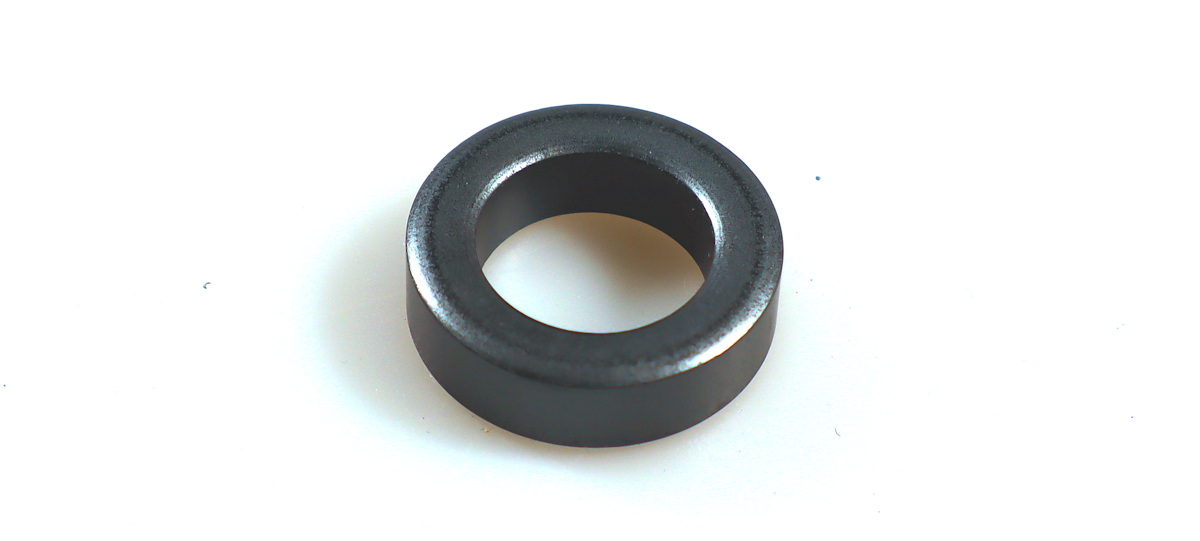
Kern FT-82-43

Kern

Kern

 
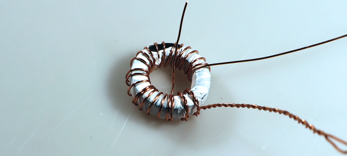
Den Kern habe ich mit 3:24 Windungen bewickelt. Im Gegensatz zum Autor des 3D Druckmodells habe ich die Wundungen umlaufen ohne der Querung bewickelt weil so der Konflikt mit mit mittleren Anschluß am BNC Stecker vermieden wird. Der Kern selbst wurde vor dem Bewickeln mit 0,4mm Draht mit einem Teflonband geschützt. Das isoliert einerseits falls der Draht beim Wickeln eine Beschädigung hat und sorgt für mehr Reibung beim Wickeln uns sicheren Sitz des Dahtes. Das Teflonband ist ein handelsübliches Band das auch im Sanitärbereich benutzt wird.
I wound the core with 3 turns and 24 turns. Unlike the author of the 3D printed model, I wound the wire around the perimeter without crossing it, because this avoids the conflict with the center pin on the BNC connector. The core itself was protected with Teflon tape before being wound with 0.4mm wire. This insulates in case the wire is damaged during winding and ensures more friction during winding and a secure fit of the wire. The Teflon tape is a commercially available tape also used in plumbing.

bewickelt
X

Der Transformator hat 3:24 Windungsverhältnis

bewickelt

Transformator fertig aufgebaut

 
Den Trafo habe ich durchlaufend gewickelt. Die bei UNUNs oft empfohle Querung habe ich nicht genutzt. So kann die BNC Buchse in der Mitte durch den Kern mit der Wicklung hindurchschauen. So braucht man auf weitere Isolierung nicht aufpassen.
I wound the transformer continuously. I didn't use the crossover often recommended for UNUNs. This allows the BNC connector in the middle to look through the core with the winding. This eliminates the need to worry about additional insulation.

Schaltung
X

Wickelschema

Schaltung

Wickelschema

 
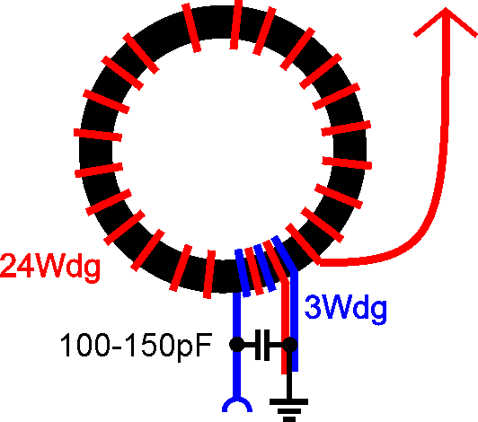
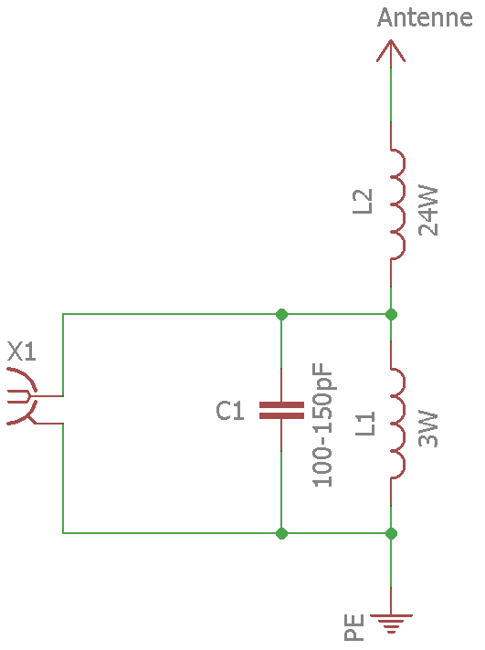
Die Schaltung ist ein Klassiker, ein Transformator am Kern 1:64 Impedanz Konvertierung um die hohe Impedanz anzupassen. Die Impedanztransformation erfolgt nach dem Quadrat der Windungsverhältnisse hier 3:24 ->1:8. Eine Endgespeiste Antenne in λ1/2 oder λ12/3 hat üblicherweise etwa 2kΩ. Der Kondensator bewirkt einen breiteren niedrigen SWR Verlauf. Der Kondensator sollte zumindest 1kV Spannungsfestigkeit haben, falls man da mal mit etwas mehr Leistung als QRP dran geht.
The circuit is a classic design. The transformer on a core offers 1:64 impedance transformation. The transformation follows the power of the winding ratio. Here 3:24 -> 1:8. An end fed antenna usually in λ1/2 or λ2/3 has an impedance of 2kΩ. The small capacitor gets you a wider usage with low SWR. The Capacitor should have at least 1kV rating. Just for savety just in case somebody uses bit more power than QRP.

Schaltung
X

Fuchskreis Schaltung

Schaltung

Fuchskreis Schaltung


3D
X

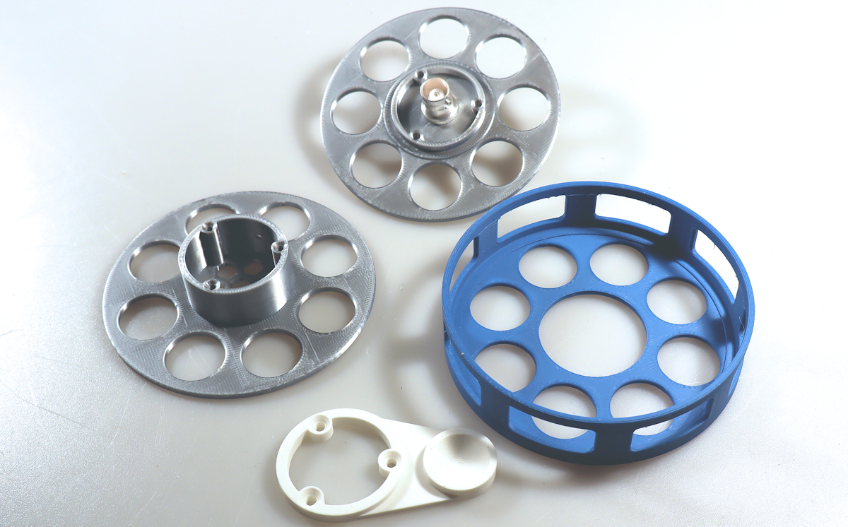
die nötigen 3D Druckteile habe ich in verschiedenen Farben ausgeführt

3D

3D Druck Teile

 
Für den Strahler habe ich den vorhandenen DX Wire Draht genutzt und gleich gute 25m auf die Trommel gewickelt. Es handelt sich um einen speziellen Antennendraht von DX Wire mit der Bezeichnung DX-WIRE "UL".

Der Draht hat 7 Liezen und eine spezielle Kunststoffseele die aus reißfestem Material bestehen. Damit ist der Draht sehr leicht aber dennoch reißfest.

Die 25m sind weit mehr als geplant, das werde ich noch etwas einkürzen wobei ich noch überlege bei welchem Band ich anfange die Antenne zu betreiben. Mit etwa 20m wäre das 40m Band und alle resonaten darüber gut versorgt.
I used my DX Wire wire for the antenna. I did about 25m into the box. It is a special wire from DX Wire with the name DX Wire "UL".

The Wire has 7 wires and a special fiber stuff. It offers special strength. So the antenna is light but allows quite a force.

The 25m is far more than planned; I'll shorten it a bit, although I'm still considering which band to start operating the antenna on. With about 20m, the 40m band and all resonant frequencies above it would be well covered.

fertig
X

auf die Spule passen 25m von dem Keflar-Draht mehr als notig, die Spule ist also groß genug

fertig

fertige Atenne

 
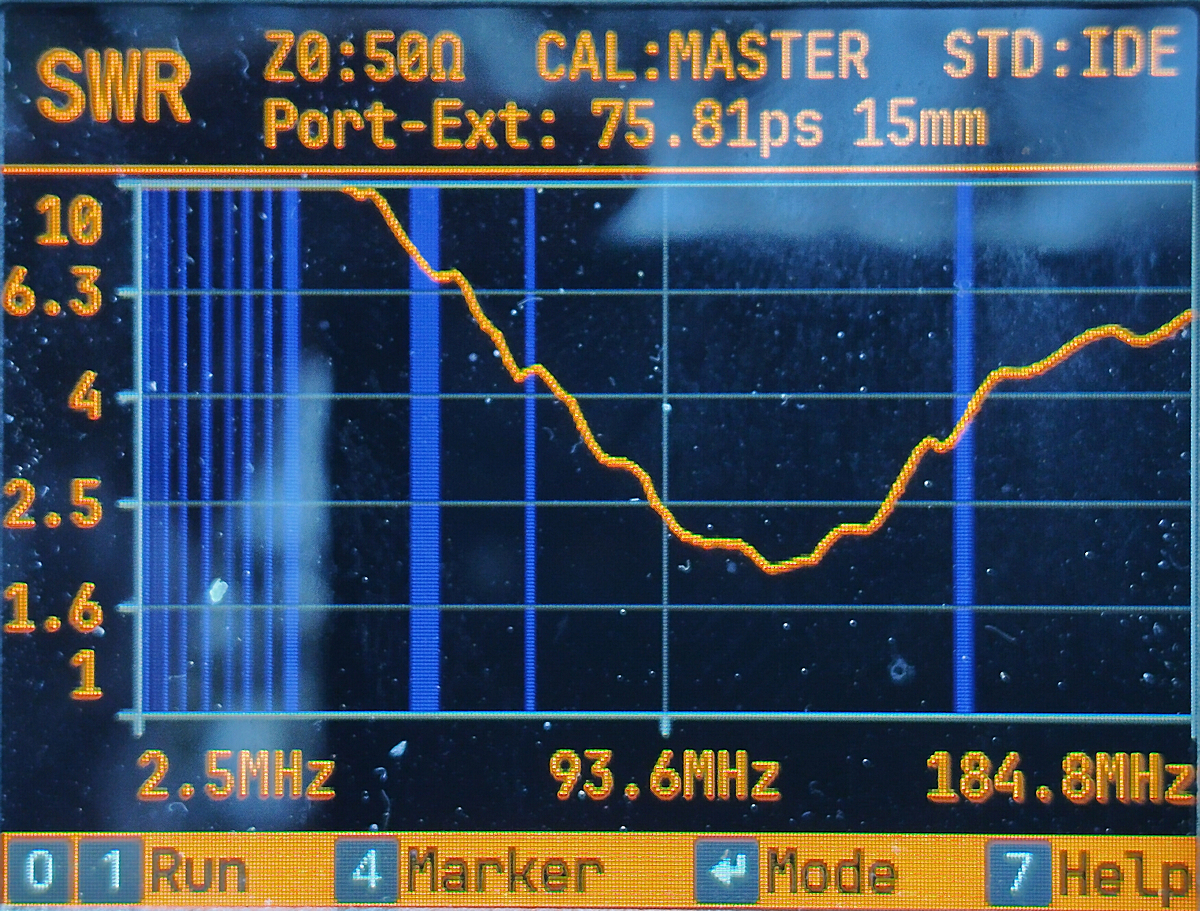
Die SWR Verläufe der zweiten Antenne. Die allererste habe ich beim SOTArieren wohl wo vergessen. Die Digitennas gibt es als 3D Druckvorschlag für 20m oder 40m Band. Der Durchmesser der Konstruktion ist unterschiedlich um genügend Material aufwickeln zu können. Für die zweite Antenne habe ich etwa 11m DX-Wire aufgewickelt und Resonanz unter 14MHz Erwartet. Das erste Nachmessen war verwirrend, siehe nachfolgendes Bild. Zunächst habe ich einen Messfehler, fehlende oder falsche Kalibrierung oder gar ein defektes Kabel. Kabel mit einer Dummyload vermessen, Messegät und Kabel waren OK.
The SWR curves of the second antenna. I must have forgotten the very first one somewhere during the SOT setup. The Digitennas are available as a 3D print suggestion for the 20m or 40m band. The diameter of the structure varies to allow for enough material to be wound. For the second antenna, I wound about 11m of DX-Wire and expected resonance below 14MHz. The initial measurements were confusing, see the following image. At first, I suspected a measurement error, missing or incorrect calibration, or even a defective cable. I measured the cable with a dummy load; the measuring device and cable were OK.

Dipol
X

dieser SWR Verlauf hat mich gewaltig überrascht!


Dipol

SWR beim ersten Nachmessen

 
Nach der Überprüfung des VNA mit der DummyLoad am Kabel war klar die Antenne hat einen Murx! Daher 11m Draht abwickeln hab' zum Abstimmen etwas mehr als nötig zunächst aufgewickelt. Dann musste die Kalelsauerei im Shack irgendwie gebändigt werdenb. Die Schaltung nachkontrolliert, alle Lötstellen OK. Nächster Schritt Bauteile kontrollieren. Trafo hat DC mäßig wie zu erwarten nahezu 0 Ohm. Dann aber der Hammer der 100pF Kondensator lieferte knapp 40pF, wobei ich noch die Messfühler in der Hand hatte. Danach Widerstandsmessung etwa 500Ω. Also das Ding ist defekt. Neuen 100pF Kondensator reingelötet. Antenne wieder zusammen gebaut und Draht aufgewickelt.

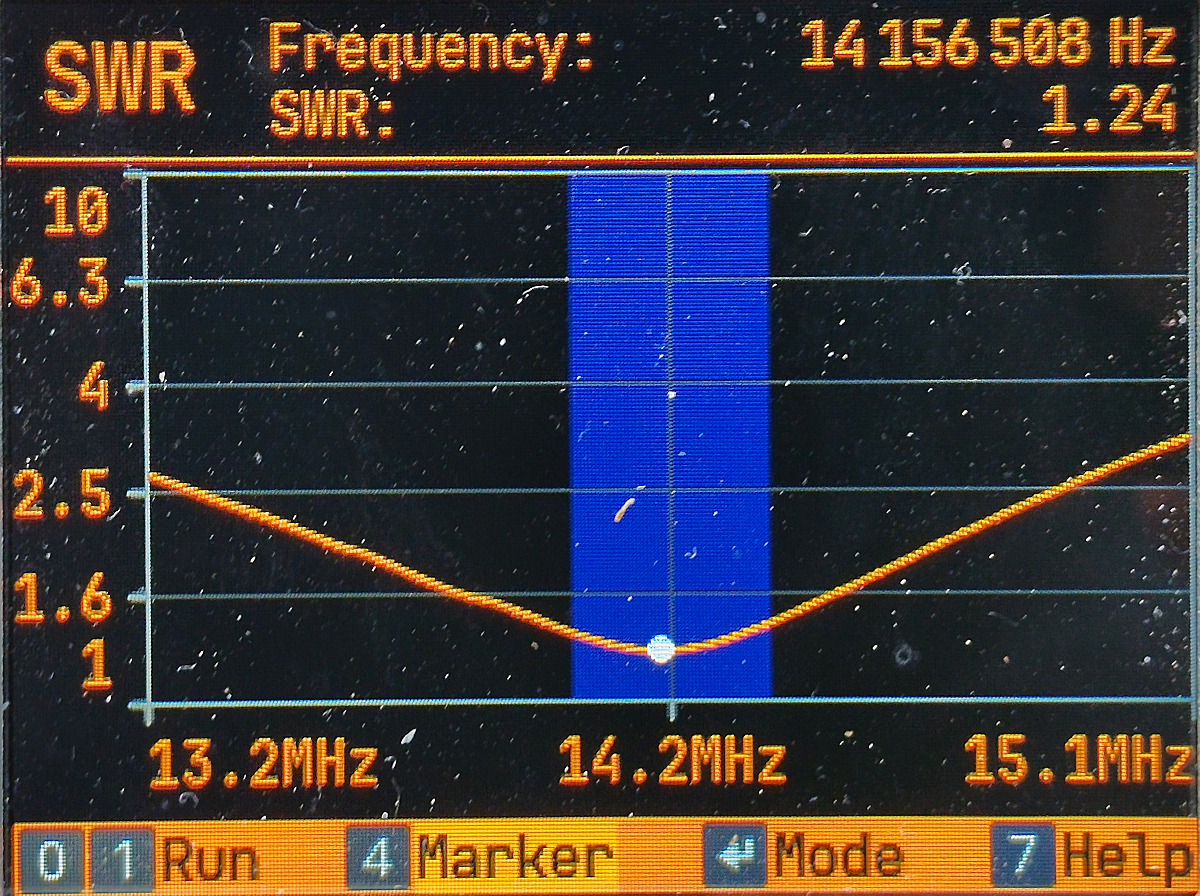
Beim Nachmessen mit dem getauschten Kondensator war das Ergebnis wie erwartet knapp unter 14MHz war das Minimum. Durch zurückschlagen des Drahtes habe ich eine passende Länge durch ausprobieren ermittelt. Später dann auf diese Länge abgeschnitten und eine Öse montiert.

Da der Draht schwer zu bändigen ist und das innere Kevlar zur Zugentlastung drin hat kann man das nicht verlöten. Die Kabelöse habe ich mit einer Andernendhülse die ich überdie Isolierung geschoben und gecrimpt habe, gesichert.
After checking the VNA with the dummy load on the cable, it was clear the antenna was faulty! So I unwound 11m of wire, initially winding up a little more than necessary for tuning. Then I had to some mess in the shack caused by the unwound wire. I checked the circuit again; all solder joints were OK. Next step: checking the components. The transformer had, as expected, almost 0 ohms DC. But then came the shock: the 100pF capacitor measured only 40pF. I still had the lines in my hand, I extpect ist was less than that. After that, I measured the resistance at about 500Ω. So the thing is defective. I installed in a new 100pF capacitor. I reassembled the antenna and wound up the wire.

When I measured again with the replaced capacitor, the result was, as expected, just under 14MHz that was the minimum. By folding back the wire, I determined a suitable length by trial and error for the intended 20m band. Later, I cut it to this length and attached a loop.

Because the wire is difficult to handle and has an inner Kevlar sleeve for strain relief, it can't be soldered. I secured the cable loop with a crimp ferrule that I slid over the insulation and crimped.

Dipol
X

schöner breiter SWR Verlauf im 20m Band. Minimum bei 1.24 so soll's sein!


Dipol

so soll es sein


© OE1IAH 2019ff site wide page calls since 2019-06-09: 7.397.698

published on: 2026 05 22