50 Ohm Dummy Load Teilesatz

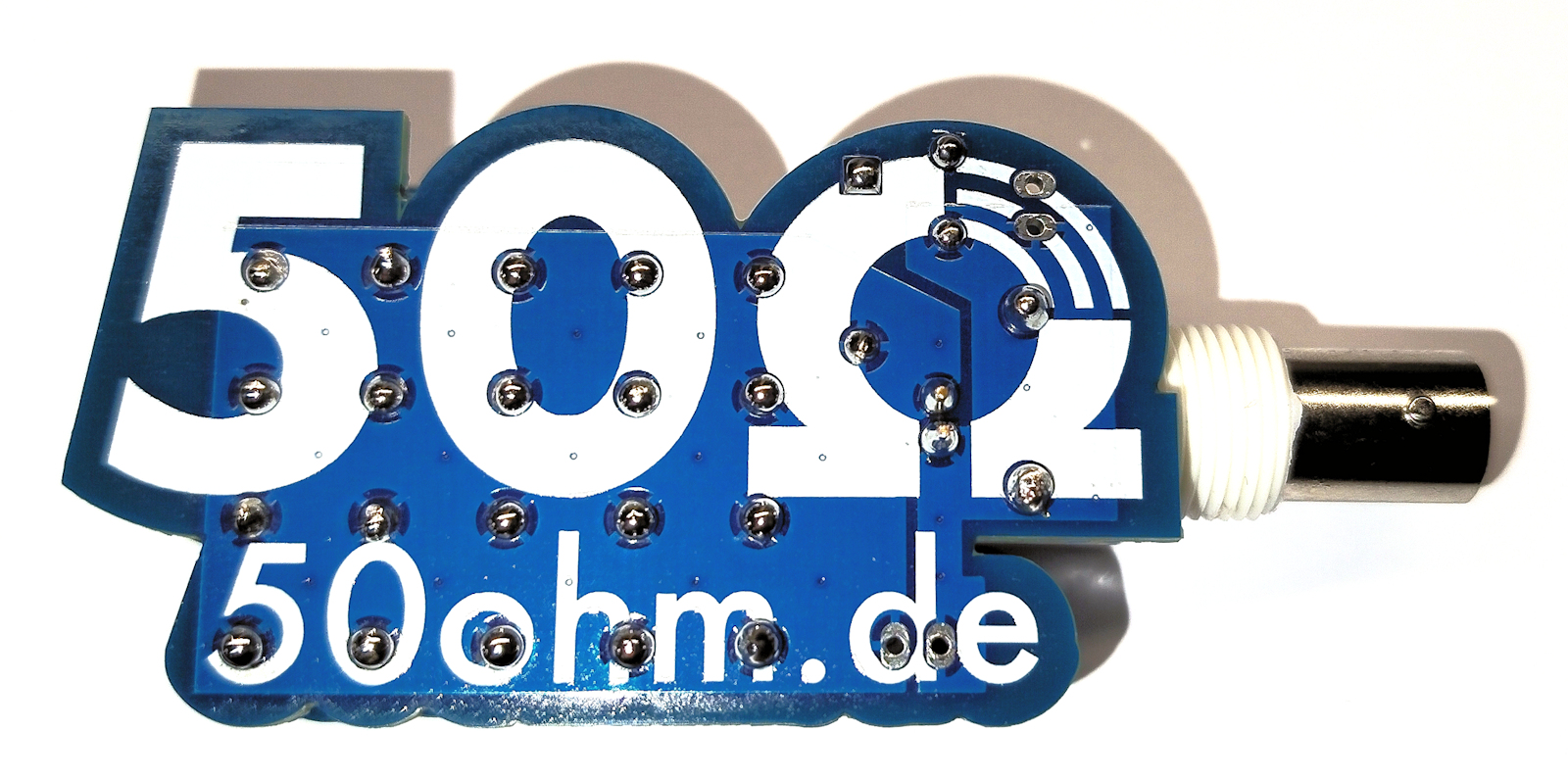
Diesen Teilesatz habe ich mir auf der Ham Radio beim auf einem Stand abgeholt. Das Konzept drängt sich auf: 20 mal 1k Widerstand parallel geschaltet fertig, da ich dann aber doch etwas mehr.

50 Ohm Dummy Load kit

I picked up this parts kit at the Ham Radio show from a booth. The concept is obvious: 20 x 1k resistors connected in parallel - done. But then there a bit more.

DummyLoad
X

DummyLoad 50 Ohm

DummyLoad

DummyLoad 50 Ohm


Dummy Loads braucht man immer wieder. Im Grunde ein Hilfsmittel zum Abstimmen oder sonstigen Dingen. Das wird auch oft als Kunstantenne bezeichnet. Dieser bausatz ist sehr minimalistisch und eignet sich durchaus auch als Lötübung für angehende Funkamateuere die noch wenig oder garkeie Erfahrung mit löten erworben haben. Der Kit ist faktisch selbsterklärend einzig die zusätzliceh Drahtverbindung zwischen ober und Unterseite ist einen kleinen Hinweis wert.

Die beiden Platinen sind vom Layout her ident. Einige der Bauteile werden nur auf einer Platine montiert wir die BNC Buchse. Die Platine hat auch einen Messausgang der durchaus überraschend für so einen einfachen Bausatz ist. Es gibt einen Halbwellengleichrichter um die am Widerstand abfallende Spannung messen zu können. Daraus lässt sich einfach die Leistung an der DummyLoad zurück rechnen.
Dummy loads are always useful. Basically, they're a tool for tuning or other purposes. They're also often called dummy loads. This kit is very minimalist and is quite suitable as a soldering exercise for new radio amateurs who have little or no soldering experience. The kit is practically self-explanatory; only the additional wire connection between the top and bottom is worth a small note.

The two circuit boards have an identical layout. Some components are only mounted on one board, such as the BNC connector. The board also has a measurement output, which is quite surprising for such a simple kit. There's a half-wave rectifier to measure the voltage drop across the resistor. From this, the power at the dummy load can easily be calculated.

Platine
X

Teilbestückte Platine

Platine

Platine


Aufbau

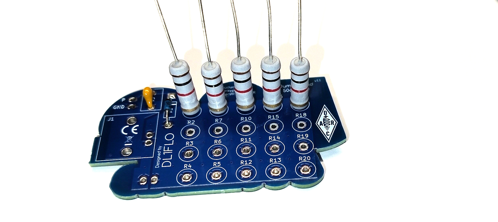
Die Widerstände werden auf einer Platine aufgelötet. Dann noch die BNC Buchse und die Diode und Glättkondensator für den Messausgang. Bei der Diode die Polarität (Das bauteil hat eine Strick Markierung auf einer Seite) das ist im Bestückungs Aufdruck gut abzulesen.

Nachdem eine Seite aufgebaut ist und auch alles verlötet ist wird die 2. Platine aufgefädelt. Wenn man die Widerstands Drähte leicht "rampenförmig" einkürzt wir es deutlich einfacher die 2. Platine aufzufädeln. Dazu die längeren Drähte zuerst einfädeln und danach die nachfolgende nächsthöhere Reihe. So rutschen die zufüreingefädelten Widerstände weniger leicht heraus. Erst wenn alle Widerstäne korrekt eingefädelt sind soll kann man auch die 2. Platine verlöten. Fehlt ein Widerstand ist eine Nachrüstung nur schwer möglich.

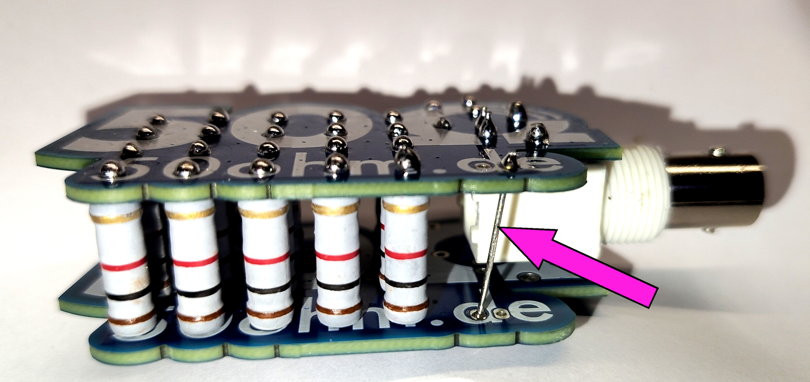
Abschließend noch die zusätzliche Verbindung zwischen den beiden Platinen einfügen - fertig!

Assembly

The resistors are soldered onto a circuit board. Then add the BNC connector and the diode and smoothing capacitor for the measurement output. The polarity of the diode (the component has a marking on one side) is clearly indicated in the component placement diagram.

After one side is assembled and everything is soldered, the second circuit board is soldered onto it. If you shorten the resistor wires slightly in a "ramp" shape, it becomes significantly easier to thread onto the second circuit board. To do this, thread the longer wires first and then the next row up. This way, the newly threaded resistors are less likely to slip out. Only when all resistors are correctly threaded should you solder onto the second circuit board. If a resistor is missing, it is very difficult to add one later.

Finally, insert the additional connection between the two circuit boards – done!

GND
X

zusätzlicher Draht für den Rückleiter zur BNC Buchse

GND

Masseverbindung


Messausgang

Auf der Platine befindet Sich eine Diode und ein kleiner Kondensatior. Damit kann man die Spannung am Lastwiderstand mit einem Gleichspannungs Messgerät erfassen.

Nach dem klassichen Leistungsformeln und dem Ohmschen Gesetzt kann man daraus leicht die Leistung berechnen oder eine Skala für ein Zeigerinstrument entwerfen das die Leistung direkt ablesbar macht. Die Spannung kann man Messen der Widerstand ist mit 50 Ohm bekannt. Die Zugrundelegende Formel lautet:
P = U2/R => oder in Worten:
P (in Watt) = (Messwert)2 / 50 Ohm

Measurement Output

The circuit board contains a diode and a small capacitor. This allows you to measure the voltage across the load resistor with a DC voltmeter.

Using the classic power formulas and Ohm's law, you can easily calculate the power or design a scale for a pointer instrument that allows you to read the power directly. The voltage can be measured, and the resistance is known to be 50 ohms. The underlying formula is:
P = U2/R => or in words:
P (in watts) = (measured value)2 / 50 ohms


© OE1IAH 2019ff site wide page calls since 2019-06-09: 8.170.051

published on: 2026 08 16